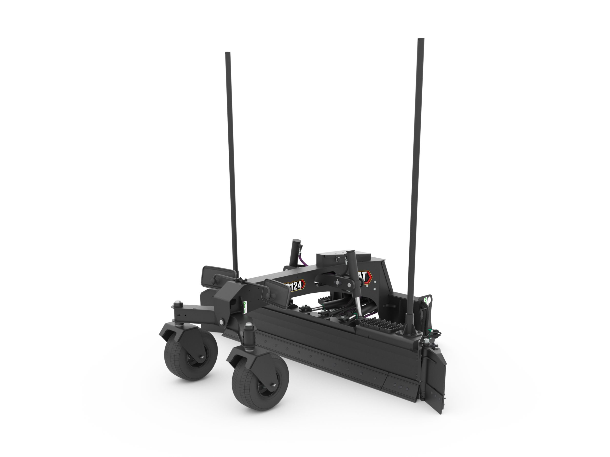
GB124 Grader Blade with Wings and Smart Technology
- Overall Width
- 102.6 in
- Blade Width
- 96 in
- Width - Fully Angled
- 105.8 in
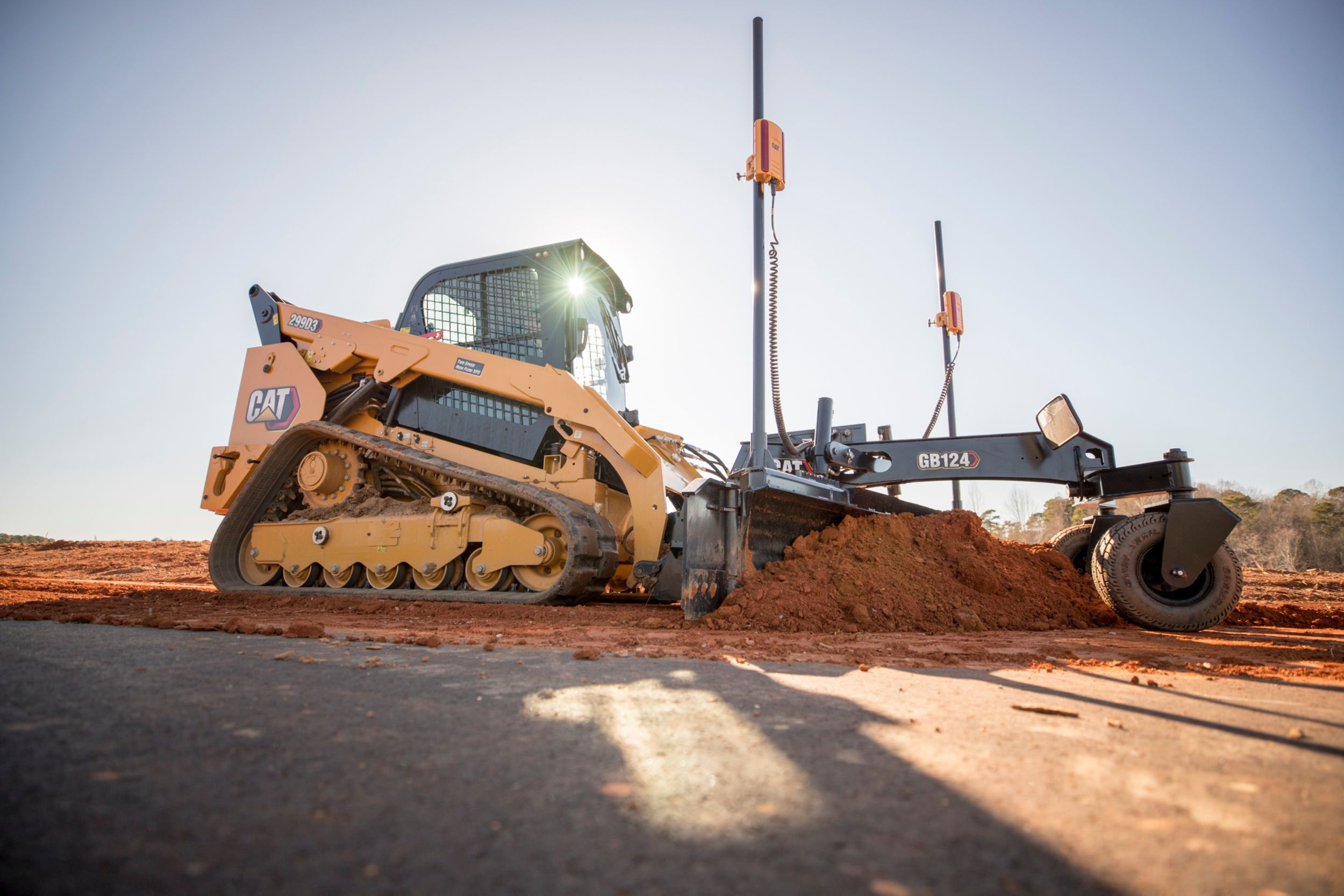
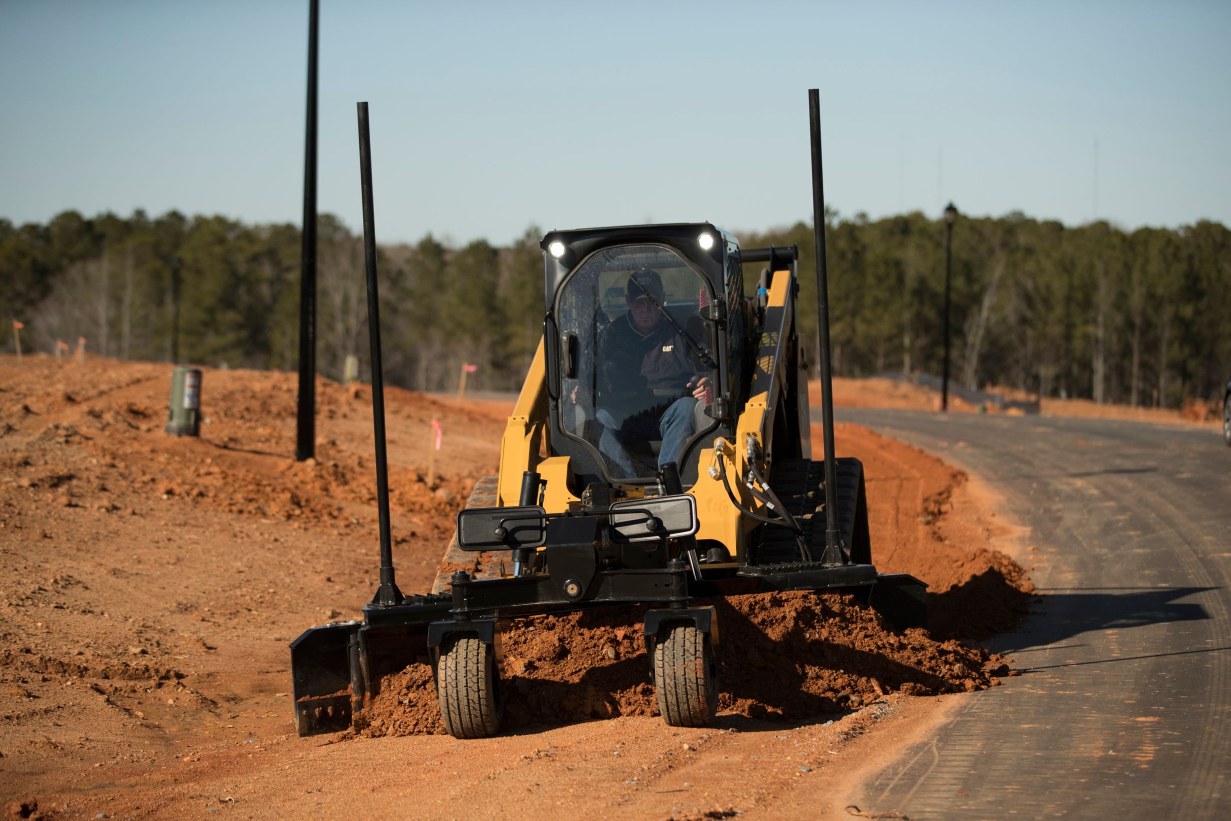
Cat® Smart Grader Blade attachments are for cutting, moving and grading dirt, gravel, sand and virtually any other material used as a base. The smart grader blade is an industry first bringing cross slope to D3 Skid Steer Loader and Compact Track Loader platforms.
Features
-
Application
Cat® Smart Grader Blade attachments are for cutting, moving and grading dirt, gravel, sand and virtually any other material used as a base. There is an assist feature of the blade that takes the unit beyond Smart. The Smart grader blade brings cross slope to Skid Steer Loader and Compact Track Loader platforms.
-
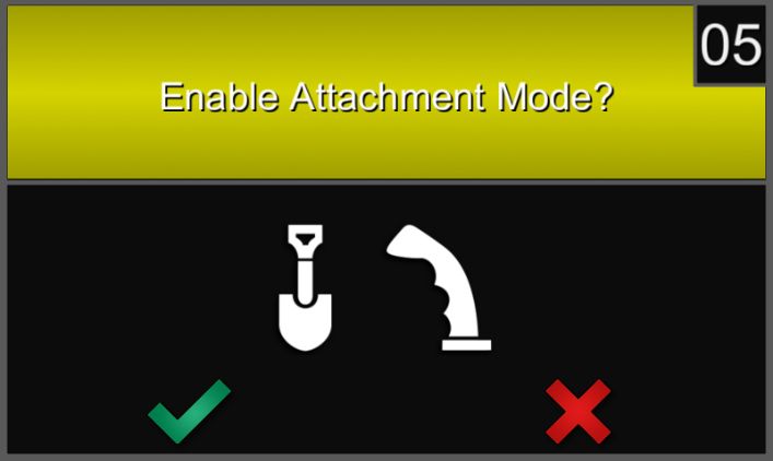
Attachment Control Mode
Attachment Control Mode (manual) turns the D3 and Smart Grader into a machine that is controlled more intuitively for the job at hand. The left joystick maintains control of the machine drive functions. The right joysticks now operate the attachment.
-
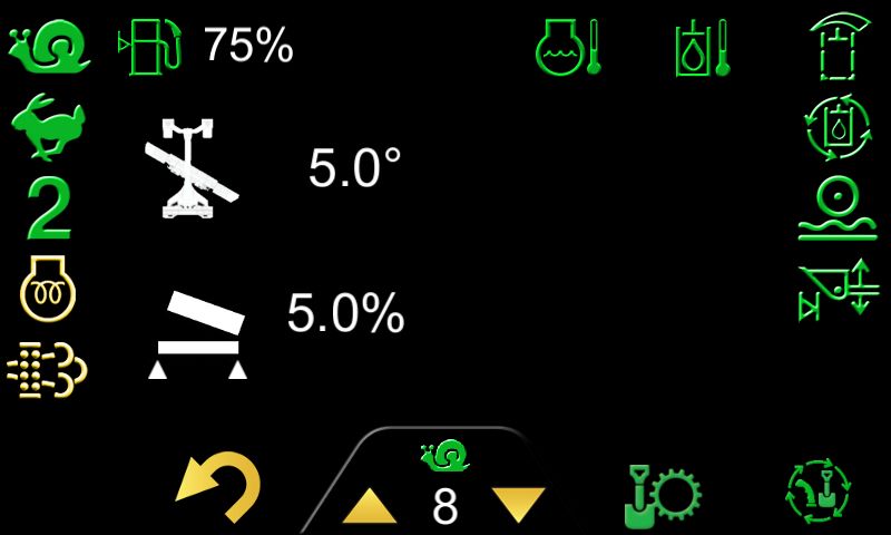
Angle Indication in Machine Display
The dedicated screen of the Smart Dozer provides the operator with feedback on the orientation of the attachment. The operator will see attachment blade slope as well as angle of the blade.
-
Cross Slope Control
With cross slope enabled, the operator selects the desired cross slope of the blade by placing the blade to the desired position. Then the attachment maintains that desired slope during operation, even when the machine slope changes.
-
External Reference Ready
Grader Blade attachment is external reference ready. Cat Grade (GPS and UTS), EW GO!, Total Station.
-
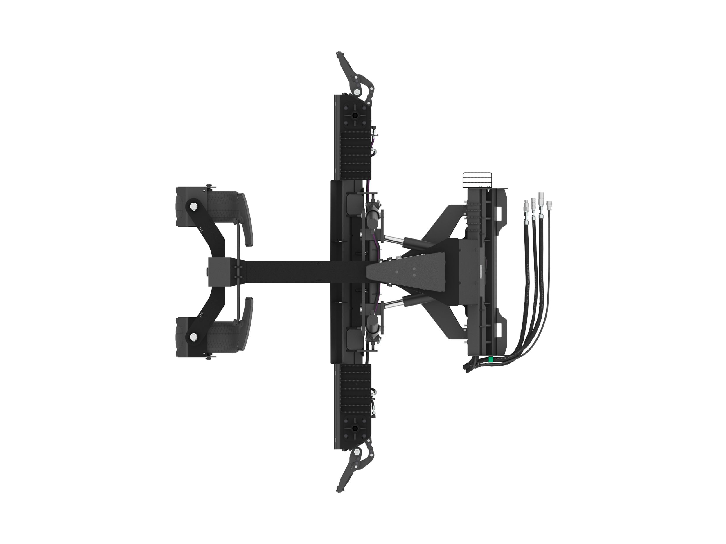
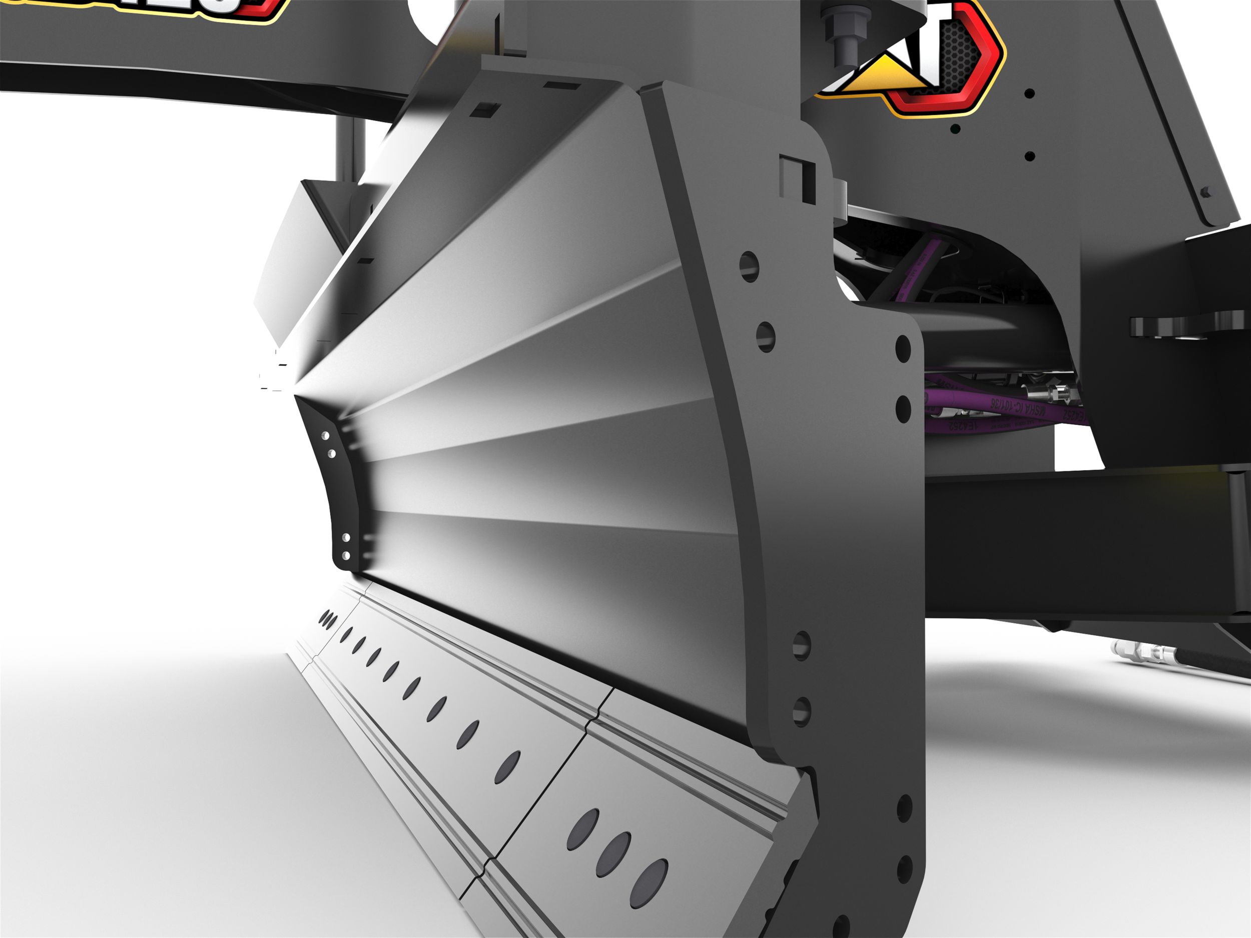
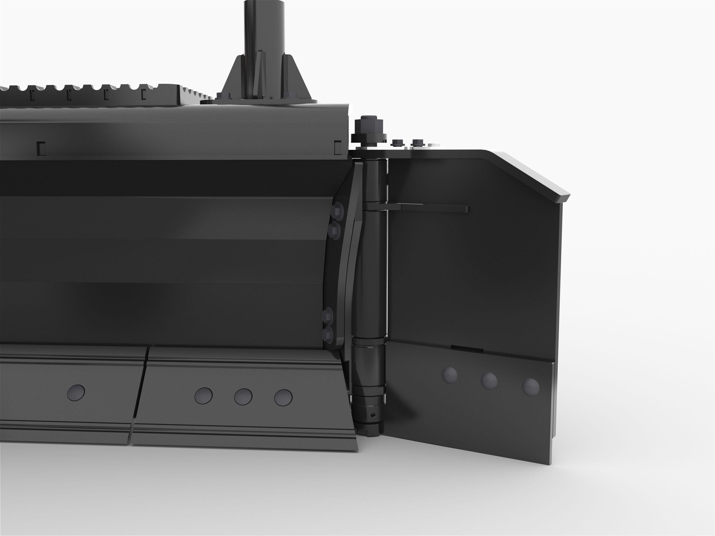
Curved Moldboard
Curved moldboard allows for material to roll and fold, improving capacity and performance. Flowing material will easily find low spots and improve grading and leveling performance.
-
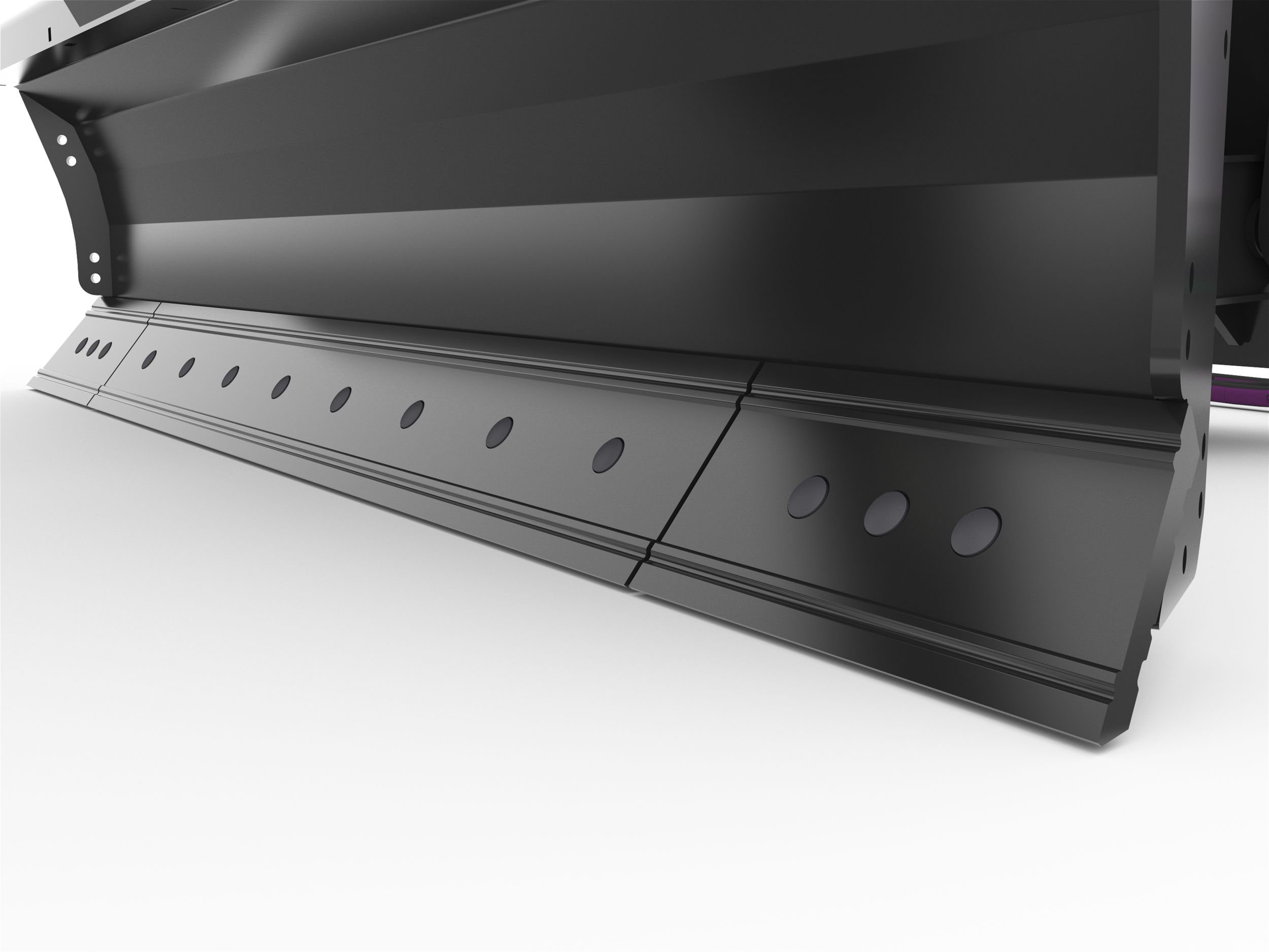
Wear Indicating Cutting Edges
Wear indicating cutting edges feature 20% more wear material on the ground engaging section of the edge and also indicate when it is time to flip (center section only) or replace the edge.
-
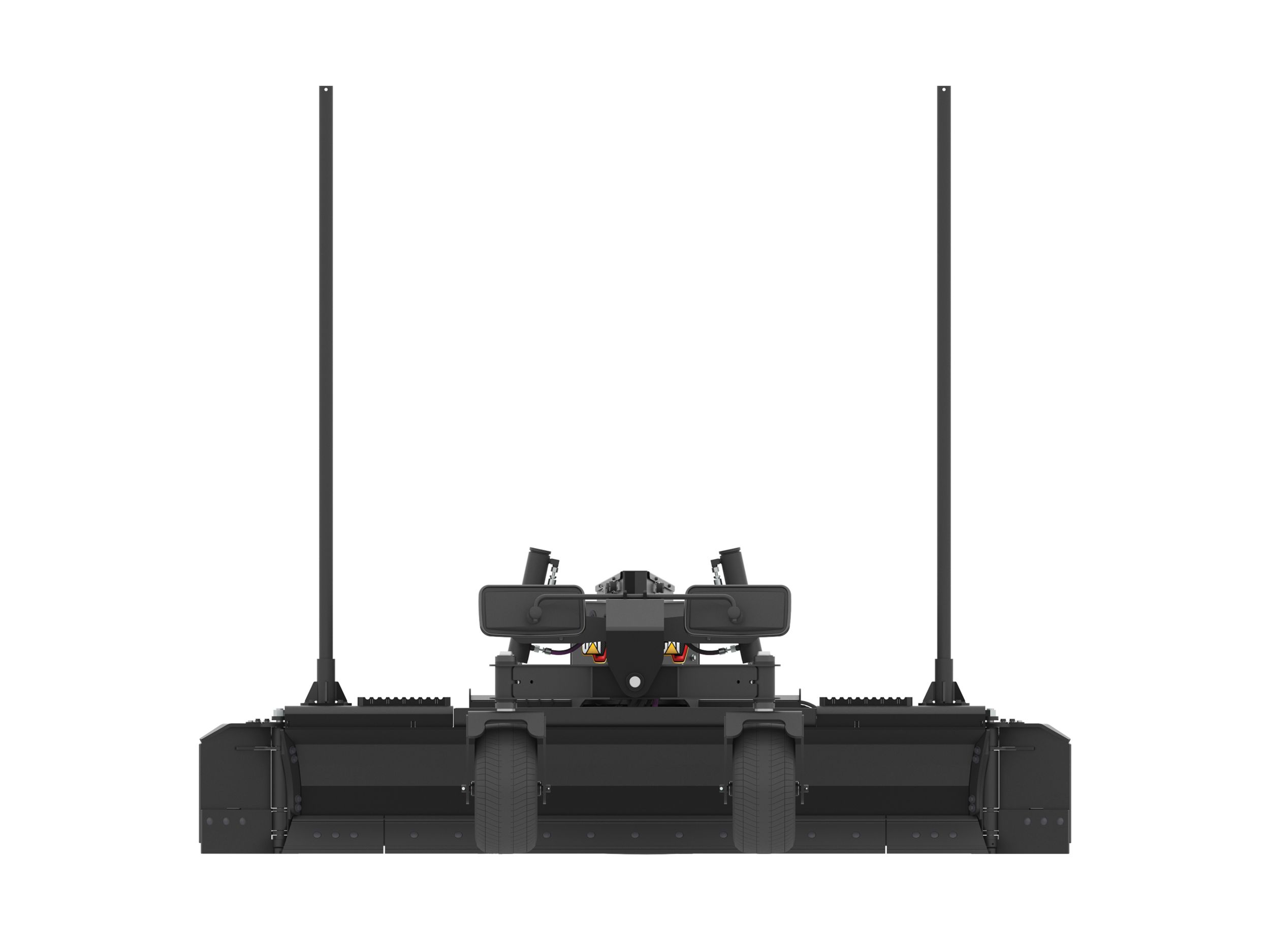
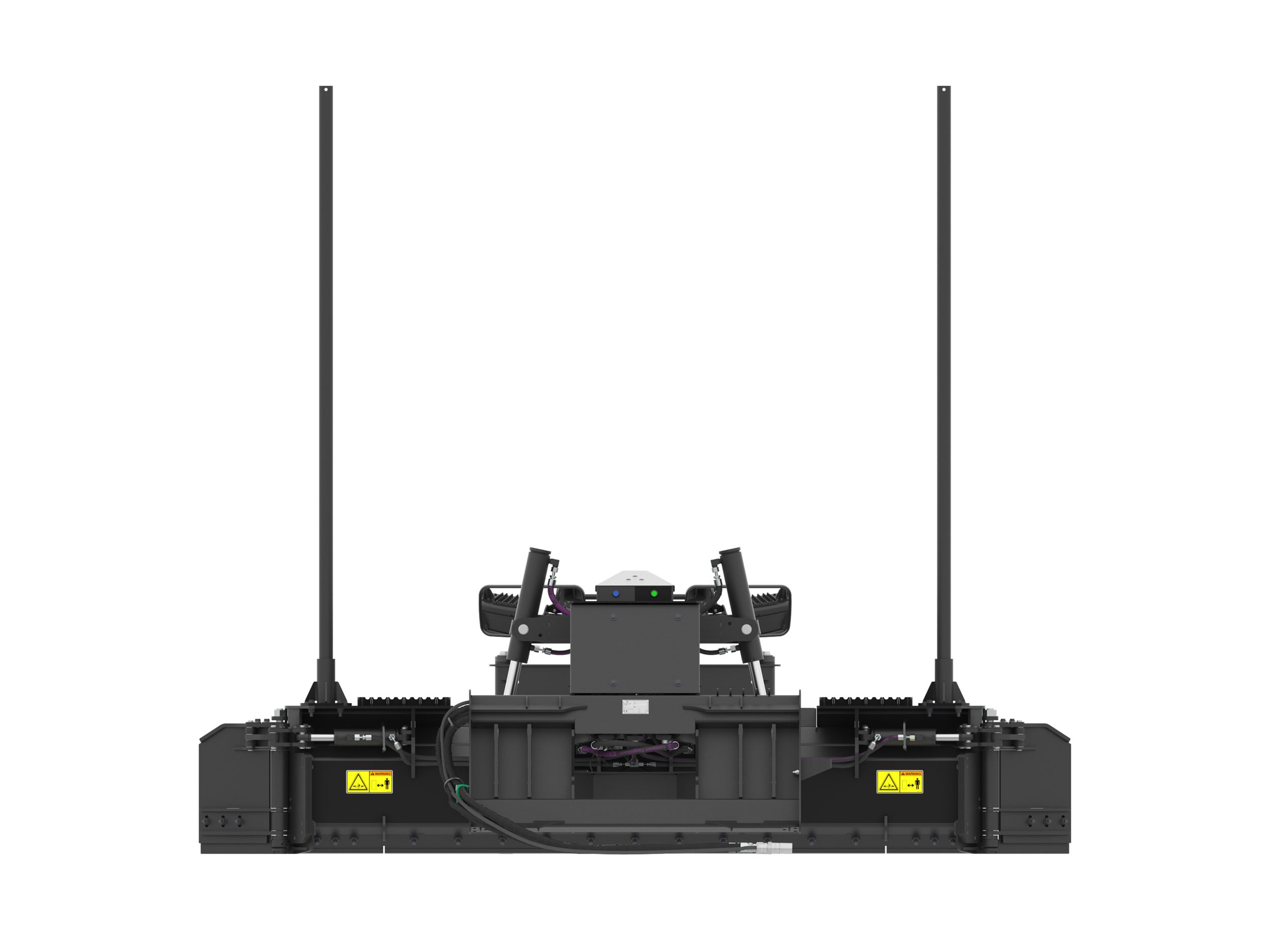
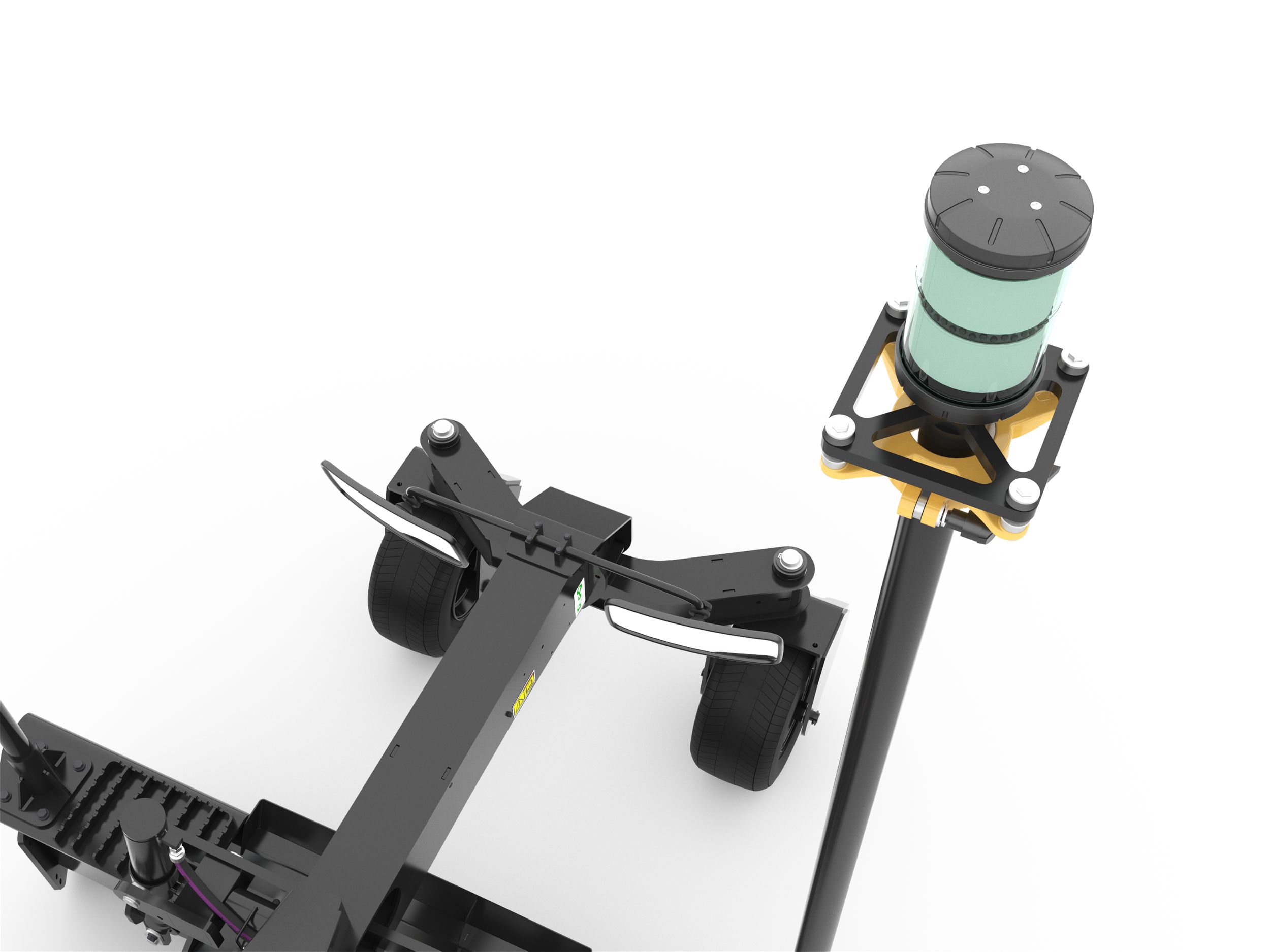
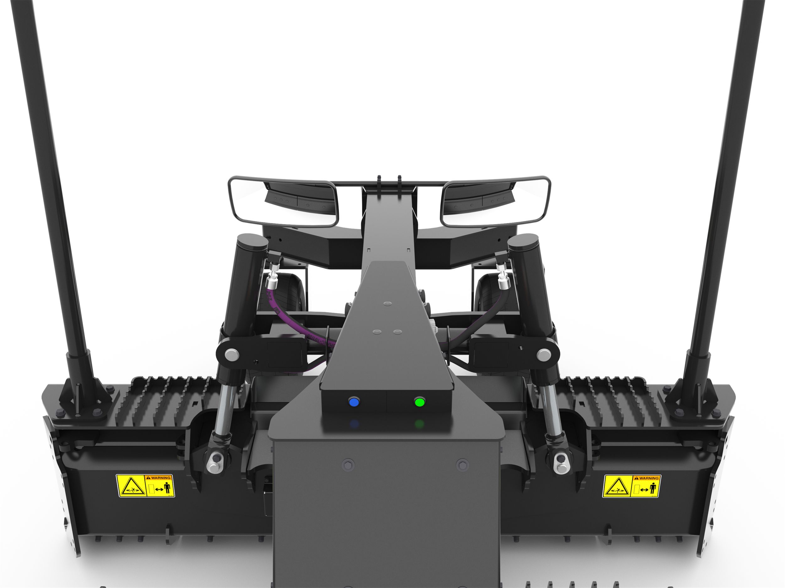
Dual Parabolic Mirrors
Dual parabolic mirrors provide full visibility to the front cutting edge allowing the operator to see how much the blade is loading and see out to the corners of the blade.
-
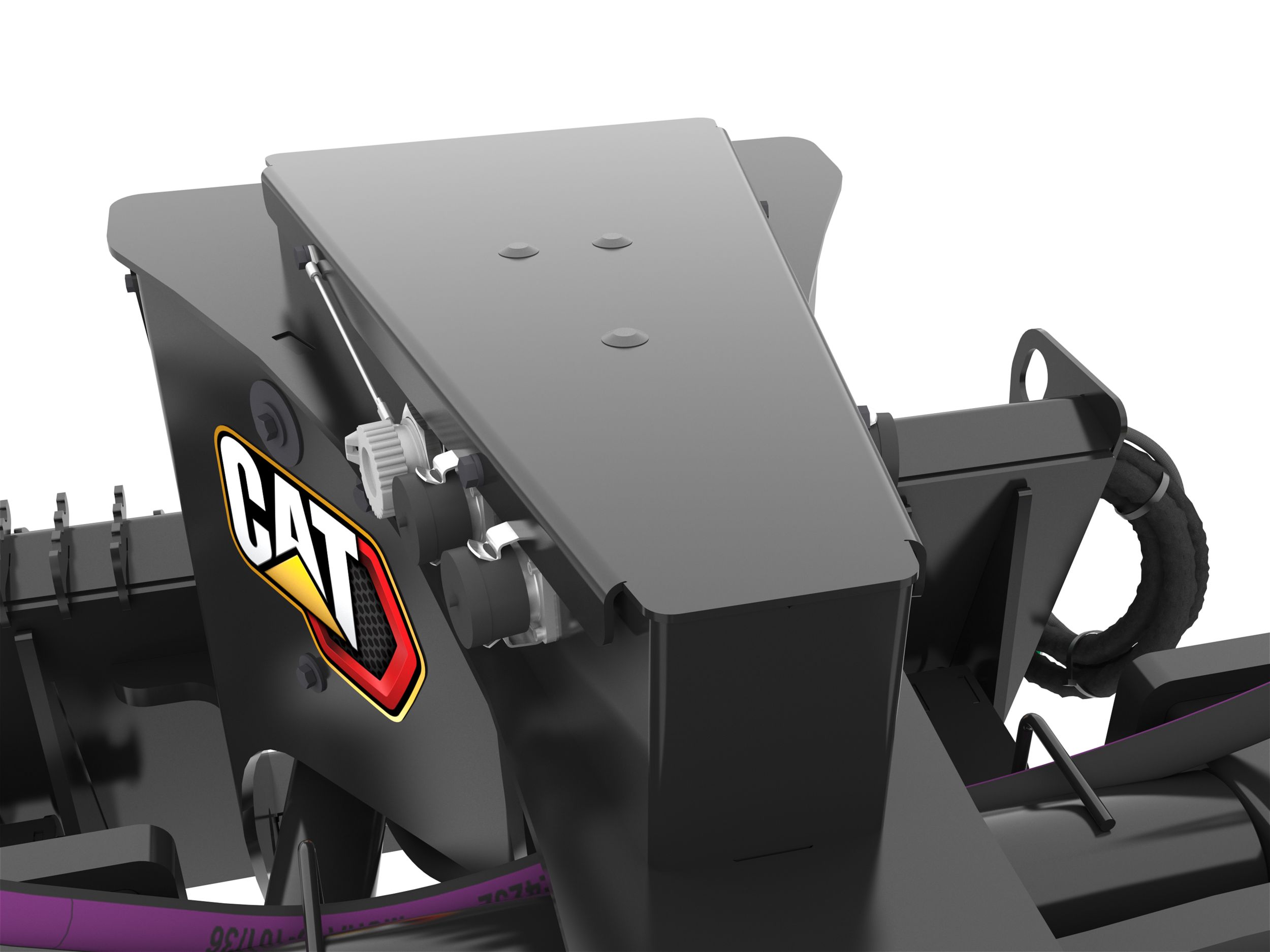
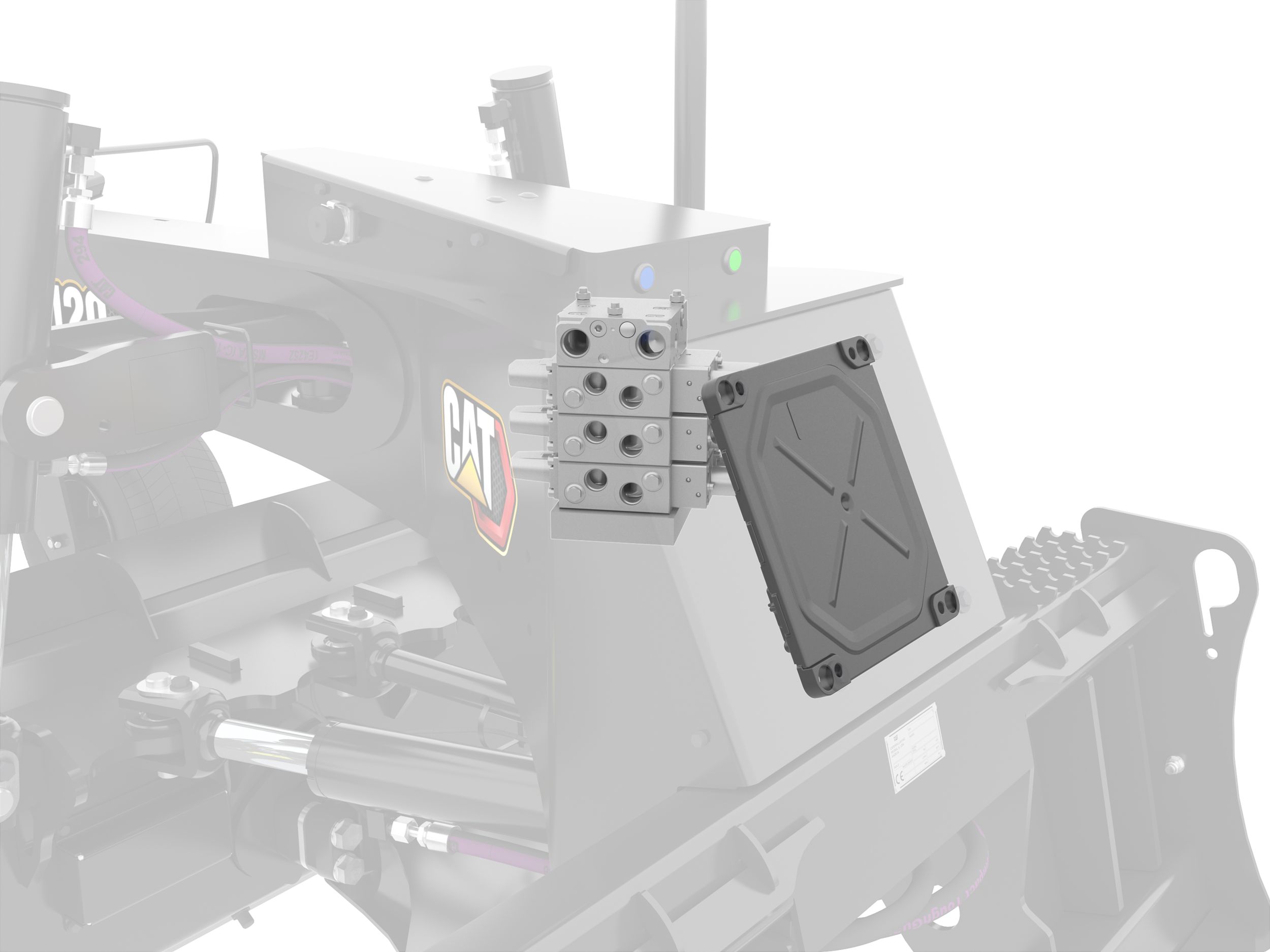
Centrally Located Electronics
Technology components are centrally located and simply route to their respective harnesses back to this location on the tool. Then, a single harness routes to the control module in the cab or on the tool.
-
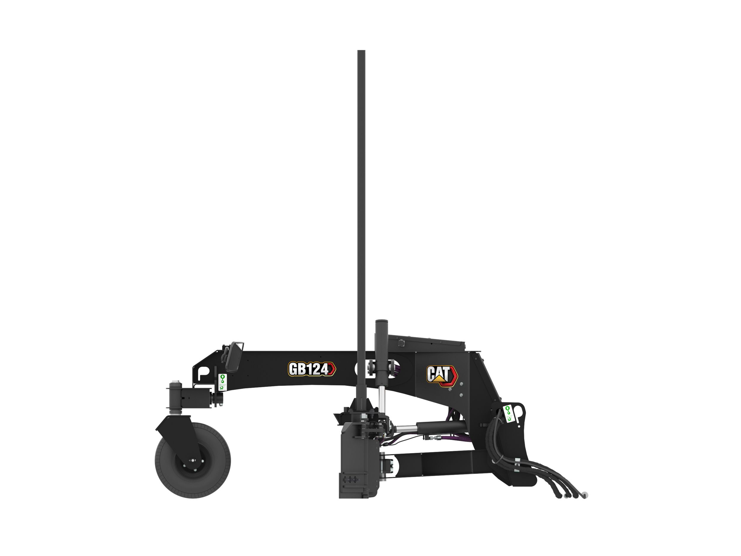
Protected Hydraulic Valve and ECM
The hydraulic valve and ECM (Electronic Control Module) are enclosed and mounted within the frame of the tool, protected from damage.
-
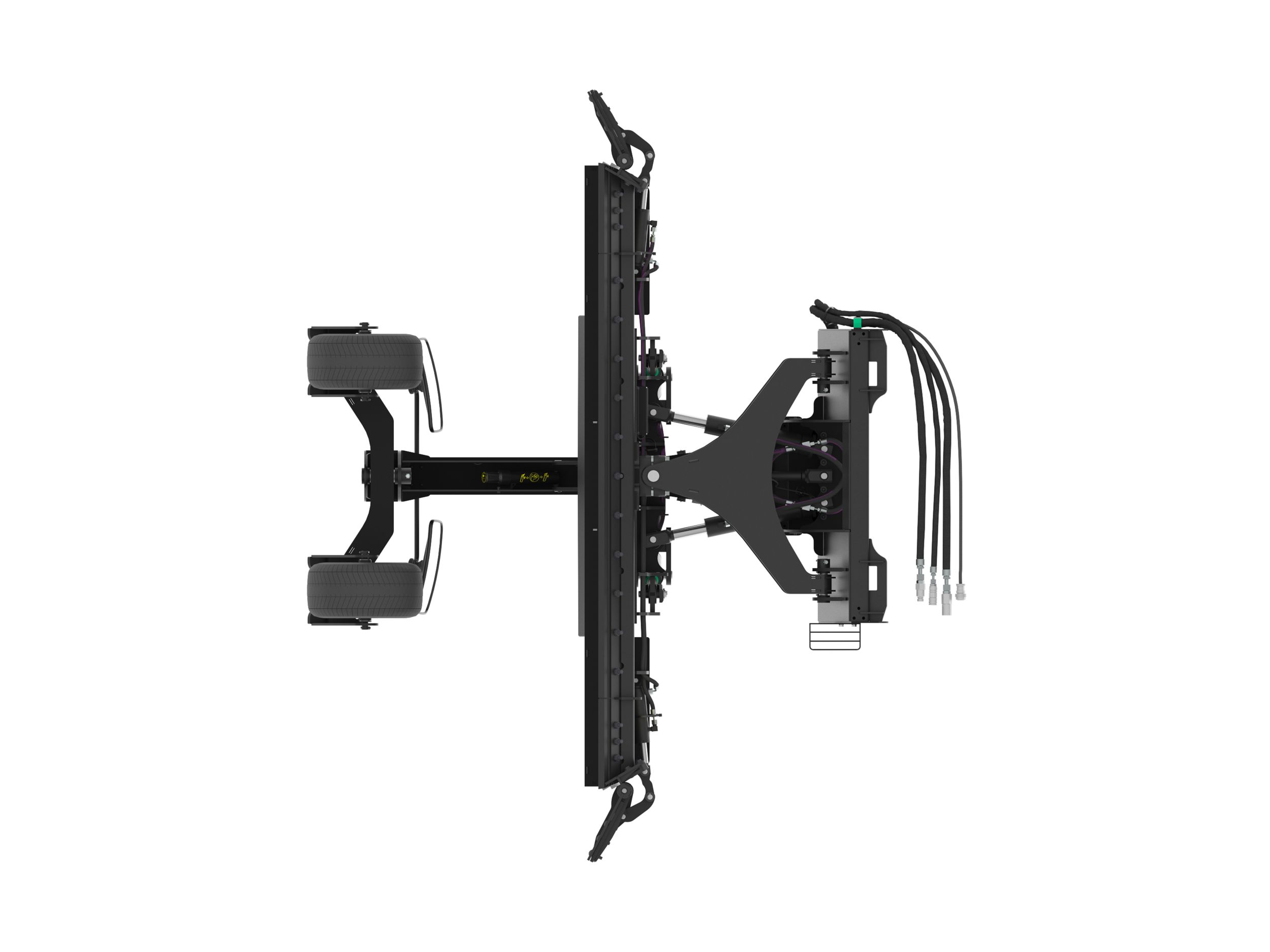
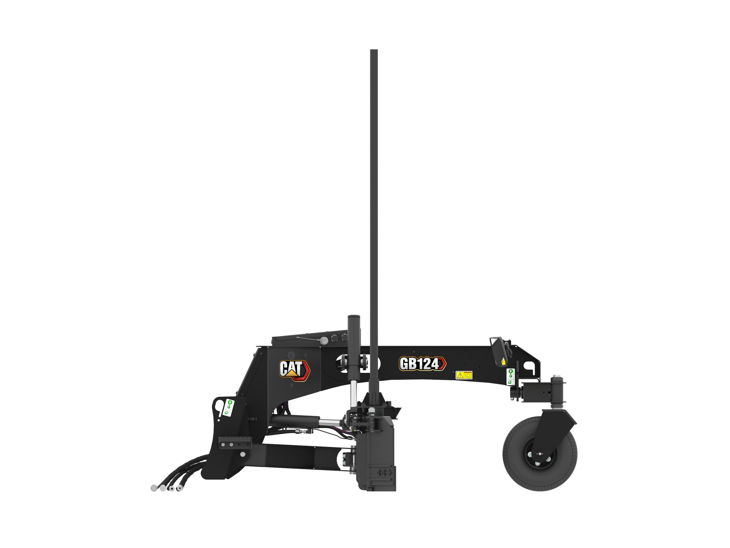
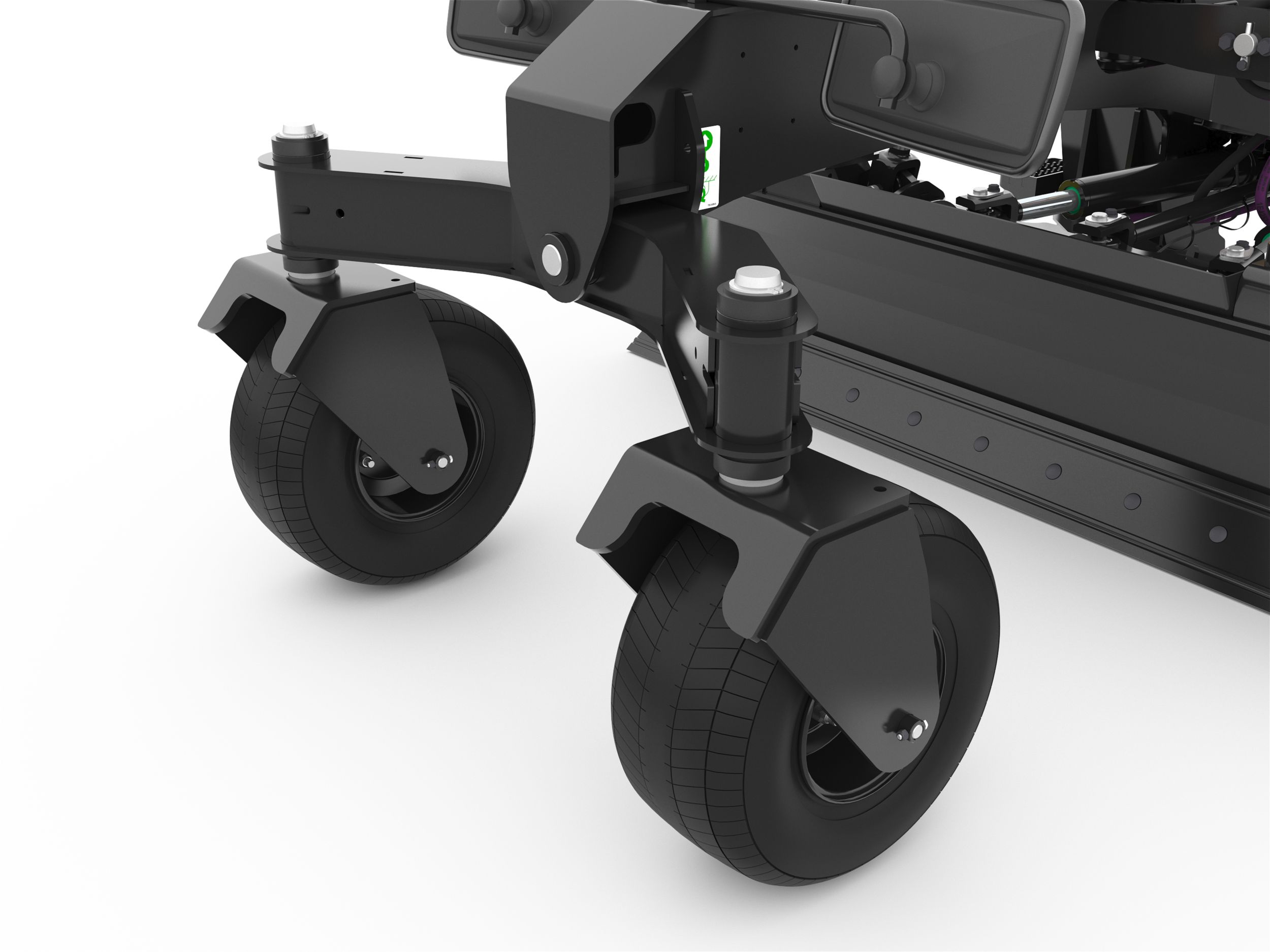
Independent Front Axle with Dual Wheels
Dual front wheels are mounted on an independent axle and on casters to provide stability in both directions of travel. These wheels are air filled and will provide balance for the blade in both automatic and manual operation.
-
Side Wings
Side wings allow the operator to make the blade wider and carry material similar to box blades.
-
Mast Mounting Points
Standard fixed masts provide great performance for single or dual laser technology configurations as well as supporting 3D technology. Bolt pattern fits Accugrade™ Std. GNSS masts.
-
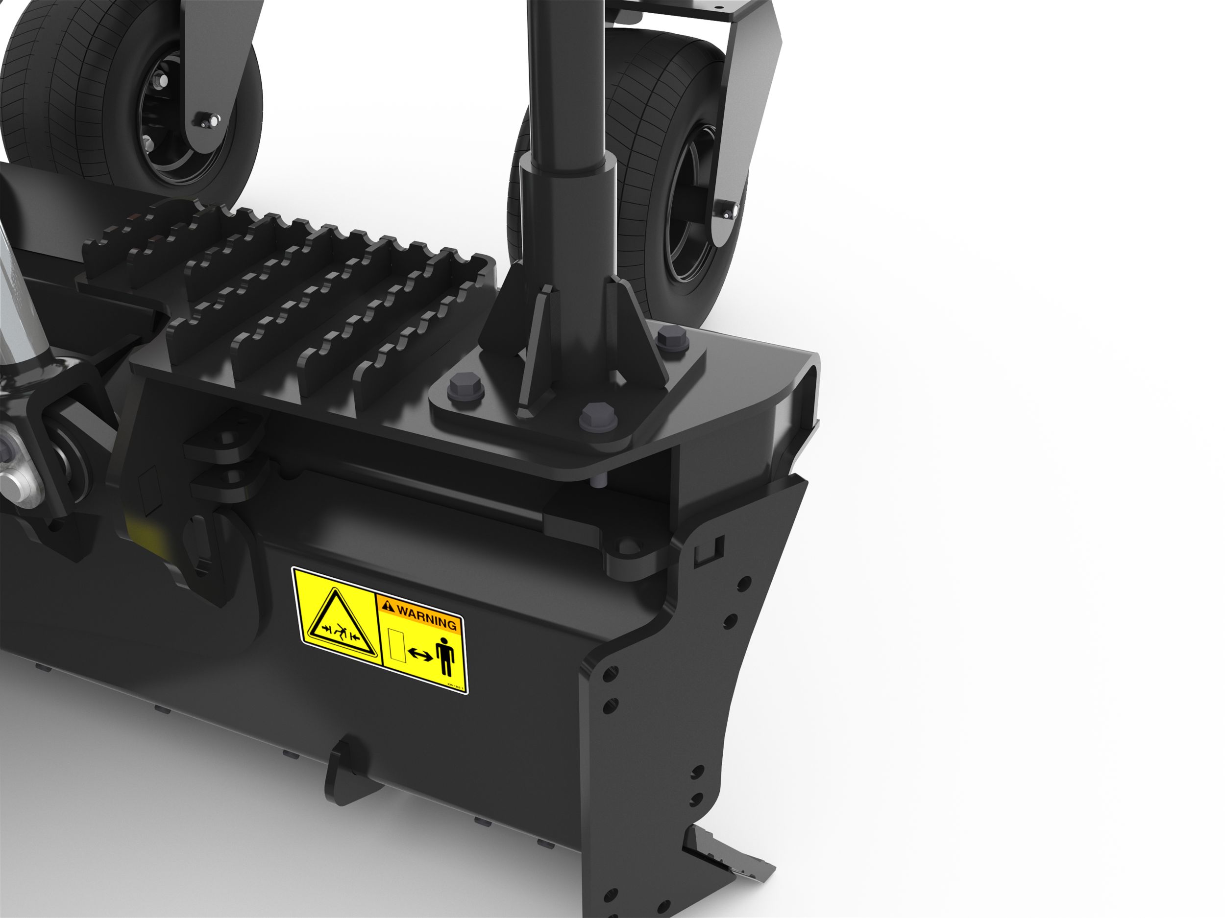
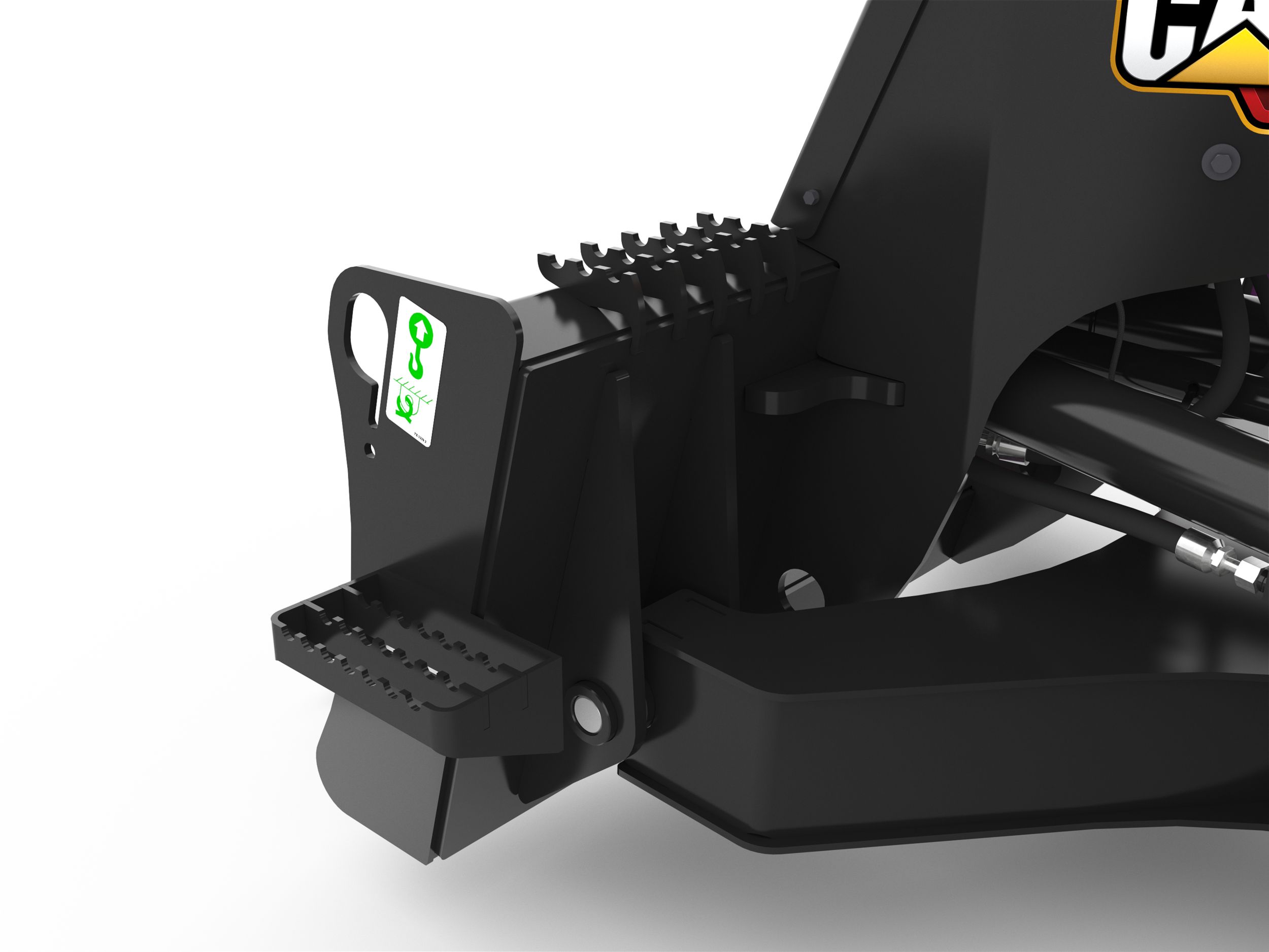
Serrated Steps
Serrated bolt-on step provides safe ingress and egress from machine cab. Additional weld-on serrated steps on the blade ensure safe receiver adjustment, install, or removal.
-
Tool Mounted Operation and Maintenance Manual Holder
Tool mounted and sealed from the elements, this holder includes all of the operation manuals and maintenance guides required for proper operation of the work tool.
Specifications
Units for specifications
General
| Overall Width | 102.6 in 2605 mm |
|---|---|
| Blade Width | 96 in 2438 mm |
| Width - Fully Angled | 105.8 in 2688 mm |
| Optimal Hydraulic Flow | 50-86 lpm (13-23 gpm) |
| Optimal Hydraulic Pressure | 180-230 bar (2600-3340 psi) |
| Required Hydraulics | Standard Flow w/14 pin |
| Overall Length | 88.4 in 2246 mm |
| Overall Height with Masts | 104.4 in 2652 mm |
| Overall Height | 41.2 in 1046 mm |
| Weight | 2292.8 lb 1040 kg |
| Tilt Angle Range | 15° Left/Right |
| Maximum Blade Angle - Right/Left of Center | 30 degrees |
| Blade Height | 17 in 431 mm |
| Maximum Cutting Edge Clearance | 6 in 152 mm |
| Maximum Cutting Depth | 4 in 102 mm |
| Interface Type | Skid Steer Coupler |
| Working Width (Wings Closed) | 102.6 in 2605 mm |
| Working Width (Wings Open) | 99.3 in 2521 mm |
| Wing Rotation | 205 degrees |
| Ground Clearance | 6 in 152 mm |
Videos
-
Cat® Smart Grader Blades | Operating Tips -
Cat® Smart Grader Blade Features and Benefits -
Cat® Smart Grader Blade at Work -
Cat® Smart Grader Blade with Assist -
Cat® Smart Grader Blade at Work -
ConExpo Demonstration of Cat® Smart Grader Blade -
Cat® Smart Grader Blader Operator Tips